Silty Water Treatment: Preventing Discharge
Water Pollution ManagementTreatment Hierarchy
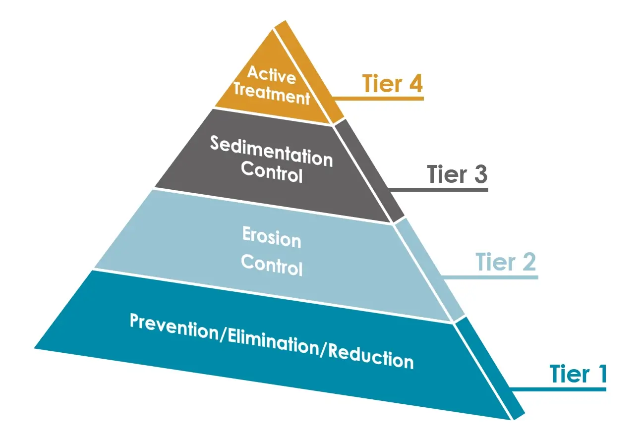
Tier 1 - Prevention, Elimination and Reduction
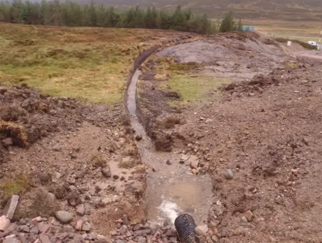
Keep clean water clean, minimise volumes of dirty water
For example:
- Phased stripping of the site
- Diversion ditches and banks to isolate the site from upland areas
- Phased and early reinstatement of the site
- Reduced site program
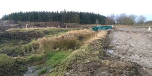
Phased Stripping of the Site
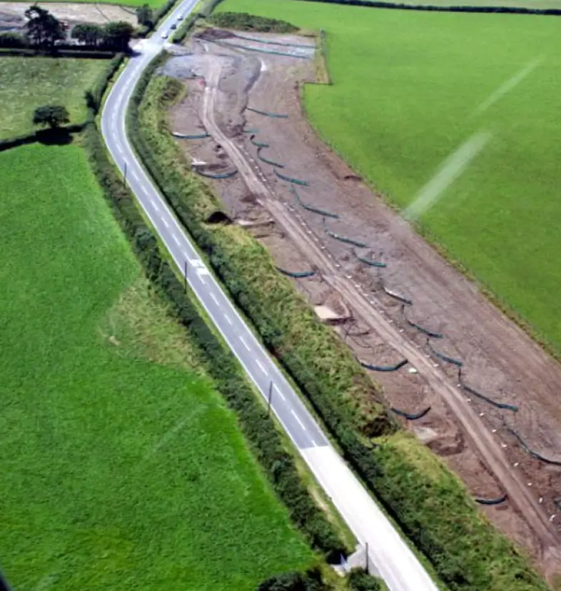
Minimise the time that soils are exposed
Reinstate/stabilise exposed surfaces as you go.
Schedule and Phase the Works
Schedule and phasing the works will limit the extent of soils exposed at any one time.
Concentrate on an area
By intensively concentrating on an area you can speedily complete this area, before exposing the next.
Limit the areas which may be exposed.
Diversions - Ditches and Banks
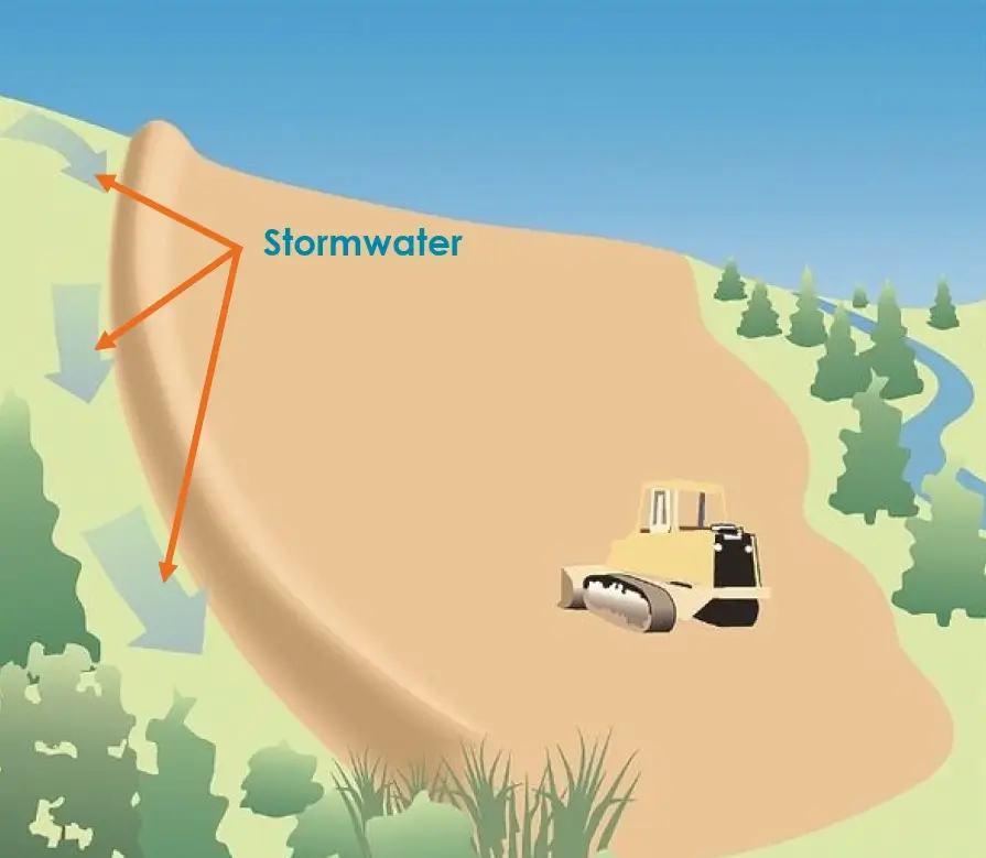
Identify any potential surface water flows entering the site.
- Divert these flows around the site
- Divert run-on and run-off away from disturbed areas
- Ensure that the diversion is protected from erosion, using vegetation, geotextiles etc
- Divert sediment laden water to an sediment trapping structure
- Use practises that encourage infiltration of rainwater
If you are working in a mountainous area a significant proportion of the water leaving your site may be derived from up gradient areas.
Tier 2 - Erosion control
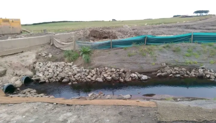
Characterised by treatment solutions which minimise the velocity at which water travels across an exposed surface.
For example:
- Silt fences
- Check dams
- Temporary reinstatement of exposed surfaces by either compaction, use of grass seeds, mulches or specialist erosion geotextiles

Commonly used to treat intermittent, small volumes of water locally to their point of production.
Protection of high risk areas.
The Second Line of Defence
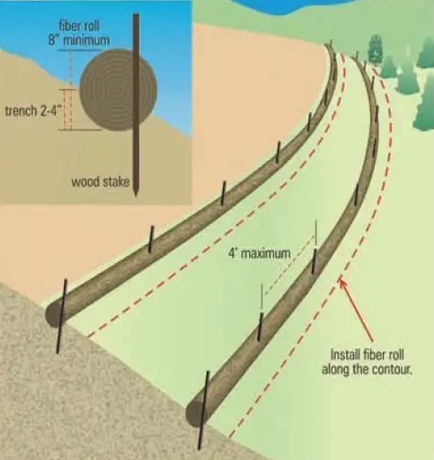
Silt Fences and Fibre Rolls
- Silt fence and fibre rolls are temporary sediment barriers.
- Designed to retain sediment laden waters from small areas.
- Not designed to handle flows from large slopes or in areas of concentrated flows.
- Not suitable for installation within the stream channel.
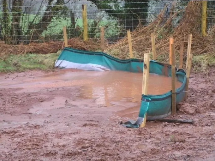
Installation of Silt Fence
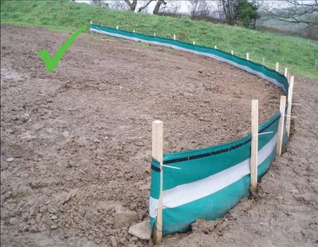
- Break the slop up into individual bays to capture the overland flow
- Ensure that the bays have sufficient curvature to prevent the flow escaping around the side
- Insert the bottom part of the fence within a backfilled trench to prevent water passing underneath the silt fence
- The number of bays required will be depends on the steepness of the slope, the area drained, the amount of rainfall
- Periodically remove the sediment that has built up in front of the fence
- Following a major storm event inspect the silt fence for damage and replace as necessary

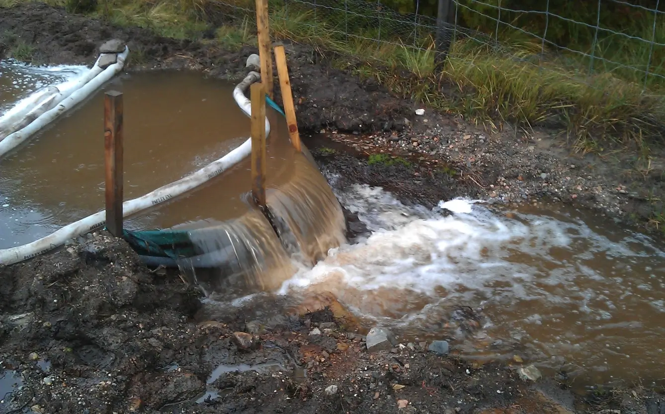
Don’t Install in Areas of Concentrated Flow
Check Dams
Check that dams reduce scour and channel erosion by reducing flow velocity and encouraging sediment settlement.
Dams may be constructed out of:
- rock
- gravel bags
- sandbags
- fibre rolls
- straw bales
- other proprietary products
Applications
- In small open channels that drain less than 4 ha.
- In steep channels where storm water velocities exceed 1.5 m/s.
- During the establishment of grass linings in drainage ditches or channels
- In temporary ditches where the short length of service does not warrant establishment of erosion-resistant linings

Infiltration Areas
The size of the infiltration area required is a function of:
- The volume of water needing treatment
- The permeability of the ground
The infiltration area needs to be covered in vegetation.
Excessive amounts of sediment in the water being treated may cause the soil to become blocked, reducing the rate at which water will soak into the ground
| Sand | Sandy loam | Loam | Clay loam | Silty clay | Clay | ||
| Range | (mm/hr) | 25 to 250 | 13 to 75 | 8 to 20 | 3 to 15 | 0.3 to 5 | 1 to 10 |
| Typical values | 50 | 25 | 13 | 8 | 3 | 5 | |
| Typical infiltration capacities | l/s/ha | 125 | 60 | 30 | 20 | 8 | 12 |
| m3/hr/ha | 450 | 216 | 108 | 72 | 30 | 40 |

From Ciria: Control of water pollution from linear construction projects. Assuming uniform distribution over area.
Tier 3 - Sediment Controls
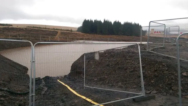
Treatment systems designed to recover suspended particles from water, prior to release into the environment.
For example:
- Gravity operated settlement tanks
- Gravity operated settlement lagoons
- Can be operated on a continuous basis
- May be used on small, medium and large flows.
- Particularly applicable for use on sites with soil particles of medium silt or greater.
- May not be effective in the recovery of colloidal, clays or fine silts
The Third Line of Defence

Settlement Lagoons, Tanks and Clarifiers
- Settlement tanks and settlement lagoons work in a similar way
- To be captures a particle must fall to the base of the tank before it travels the length of the tank.
- The flow rate which you can treat is defined by the following equation:
Q = V x A
V = Particle Settling Velocity (m/hr)
A = Effective Settlement Area (m2)
Area vs. Settlement Area


Settlement Area may be:
- Less than the plan area
- Equal to the plan area
- Greater than the plan area
Connecting Modules Together (Wrongly)

If area of Tank A = Area of Tank B,
little additional solid removal occurs in B

Connecting Modules Together (Correctly)

Each module receives half the flow, therefore better water quality is obtained as both tanks will collect sludge.
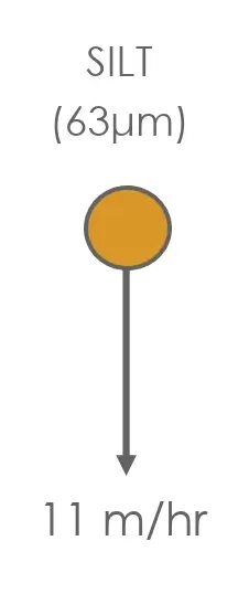
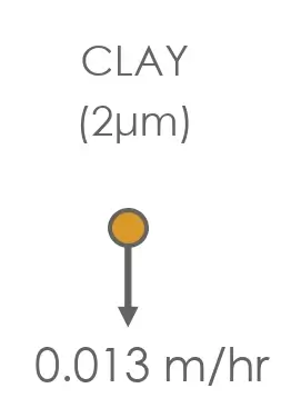
Settling Velocity - A Function of Particle Size
| Material: | SAND | SILT | CLAY |
| Typical diameter: | (2mm) | (63μm) | (2μm) |
 |
 |
 |
|
| Settlement area proportional to settling velocity Sand to clay variation of 100,000(!) |
|||
Maximise Area to Reduce Flow Rate
| Diameter | Settlement Area | Area for 50m3/hr | |
| Gravel | 2mm | 0.02m2/m3 | 1m2 |
| Sand | 63μm | 0.1m2/m3 | 5m2 |
| Medium silt | 20μm | 1m2/m3 | 50m2 |
| Fine silt (cement) | 10μm | 5m2/m3 | 250m2 |
| Clay | 1μm | 100m2/m3 | 5,000m2 |
(Based on a particle density of 2.65t/m3)
Summary
- Where possible choose a treatment solution from a lower tier over one from a higher tier
- If an adequate water quality is not being achieved, the plan must be amended
- Every treatment solution has an operating range, fit the problem to the solution – don’t force the solution onto the problem
- Select a level of control appropriate to the environmental setting of the site

Simon Skentelbery
General Manager
John F Hunt Regeneration Ltd
London Road
Grays
Essex
RM20 4DB
M: 07967 306 517
E: simon.skentelbery@johnfhunt.co.uk
W: johnfhuntregeneration.co.uk